Friday, August 7, 2015

Episode 5

I'm back!

I've been a ghost for a few days because work has been keeping me very busy, but I have still been working slowly on the hive.

One of the issues I had to address in this build is a new component which wasn't in my other hive.  Since I want to be able to harvest honey from this hive, I need to include a queen excluder.  A queen excluder is a piece you put between the main hive body and any frames you want to harvest from.  As the name suggests, it acts as a "queen filter" preventing the queen from accessing frames.  That means she won't lay eggs in these frames, and the bees respond to this by using the frames exclusively to store honey.

Queen excluders take advantage of the fact that queens are larger than worker bees, so they have small slots which are large enough for workers to move through, but too small for queens to squeeze through.  I originally planned to build my own by gluing metal rods in a wooden frame, and had researched the proper spacing required.  However, I found that Brushy Mountain Bee Farms sells a plastic excluder, so I decided to buy one and cut it up.

First, I cut and slotted pieces which match up with the length of beelocks.  The queen excluder will sit above the upper beelock and below the top two frames.  These two frames will be my honey frames.


Just like the beelocks, I added a spacer between the two slotted beams.  Unlike the beelocks, this piece will only have one layer - It will contain strips of queen excluder donated from the plastic piece I purchased, and a slot for installing a plexiglass strip to close off the top two cartridges.

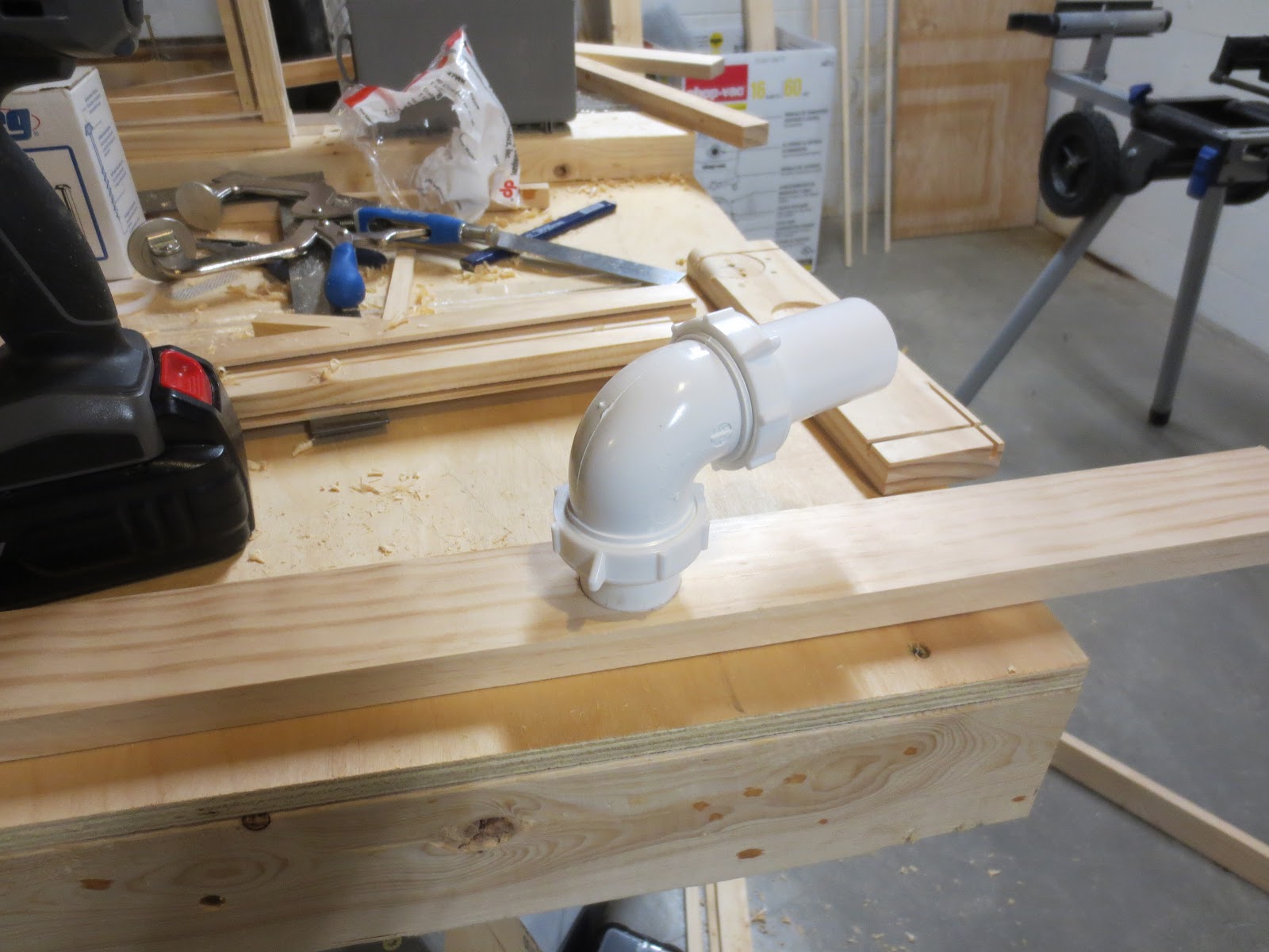
I used my oscillating tool with a crescent saw attachment to cut out strips from the donor excluder.

Then I slid the donated strips into the new queen excluder.  One row of slots fits inside the beespace.

One queen excluder ready to go!

Now that all pieces of the hive frame are put together, it's time for the assembly.  I had been holding off on this part, since it's the greatest risk for failure.  I have to get all functional components of the hive mounted, secured, squared, properly aligned, and properly spaced so they accept the cartridges smoothly.

Of course, I have a plan to work from, so luckily I know how the parts need to fit together.  Below you can see an overview of how the hive will go together.  There will also be cabinet doors on front and rear of the hive.


For this final construction, I've switched from glue construction to pocket holes.  I need this frame to be solid, and also I will probably need to unscrew and make modifications to pieces as I go.  Luckily my Kregg jig makes pocket holes easy and flawless every time.

Three beelocks mounted to the front cabinet sides, including the beelock with the feeder housing.  I'm using cartridges to make sure the beelocks are spaced correctly, and a square to make sure all pieces are aligned with each other.

All beelocks mounted, and beginning the inner joists.  These will add strength to the structure and also act as the doorstop for the inside edge of the cabinets.  I bought magnetic latches for the cabinet doors which will mount on the interior side of these joists.

All front-side cabinet joists mounted, all cartridge slots tested.  Some are a bit too snug, but I'll be solving this with some sanding.  Too snug is better then too loose, we don't want bees escaping into the house!

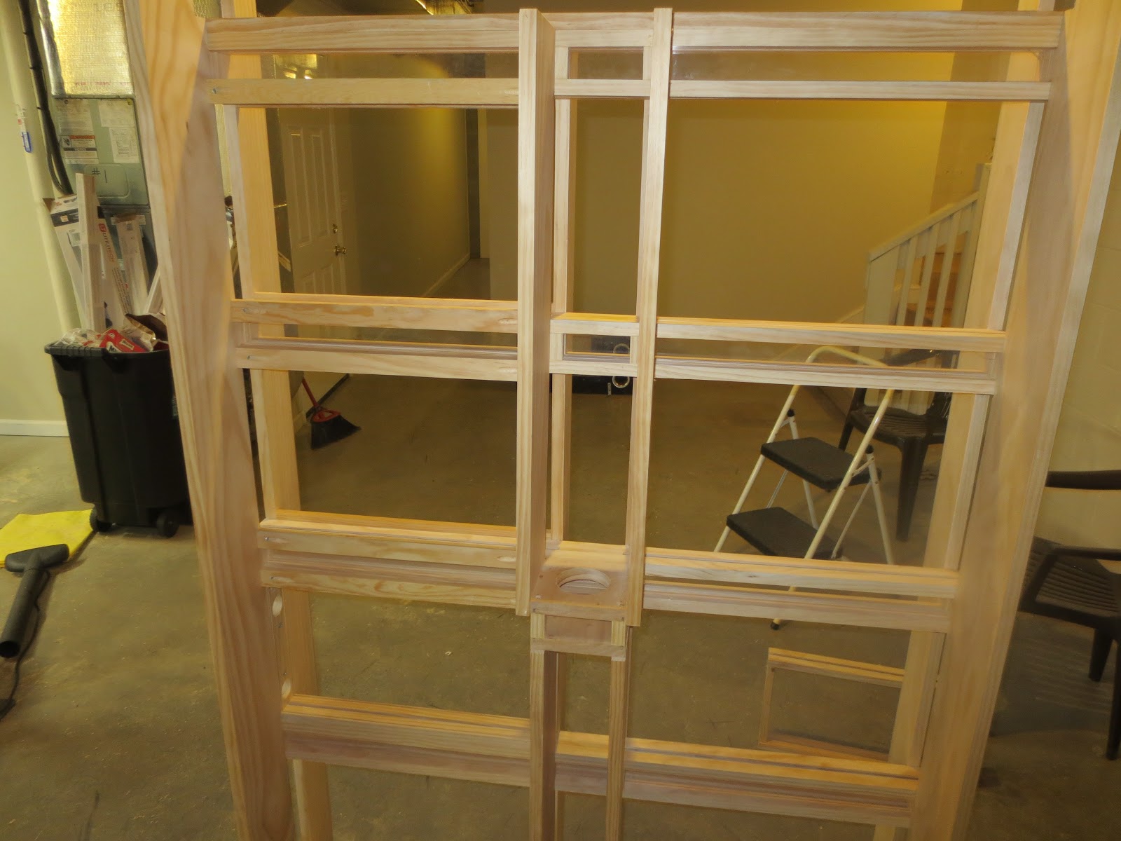
Next up, flip it over and repeat on the backside.  Since this side does not have a feeder housing sticking out, it is shallower.  You can see how the cartridges will slide in between the front and back cabinet mounts.

The first picture of the hive in its upright position.  I'm very relieved to have it standing up, because it means I also get to stand up while I work on it.  Crawling around on the floor is not as easy for me as it was when I was a teenager...

For added security and ease of installation/removal, I'm adding guidepieces top and bottom.  This keeps the cartridges centered perfectly over the beelocks.  There will also be backstops the cartridges will butt up against, but I will not be adding them until I finish the external locks.  More on those later.

In this shot you can see the guidepieces in place on most of the slots on the left.  The slots on the right have not had their guidepieces installed yet.

As you can see from a sideview with two cartridges in place, the bees would have plenty of room to escape where the cartridge slots fit.  Therefore, I've decided to mount external locks around each beelock.

To do this, I'm cutting short pieces of scrap wood left over from building cartridges and beelocks. (I have a lot of this, so it's great to get use out of it!)  Then, I used my dado blade to cut two recesses in the piece.  It looks very much like a lincoln log at this point...

Next, I drilled three pocket holes on each piece, and mounted it to the cabinet joists.  With these pieces in place, I can slide plexiglass strips under the recesses in each piece.  This both locks the cartridge in place, and blocks off the slot holes.  

That's all for this episode, but since it's Friday I'll have more content soon.  I plan to get a lot more work done on the hive over the weekend!  Thanks for reading.

Thursday, July 30, 2015

Episode 4

Hello again

I haven't posted for a few days because I've been building more cartridges, not much new content involved for that.  However, I completed the exit housing yesterday - this is the piece which will fit in the window.  I cut all the parts before putting this together, below you can see the top and bottom, along with the much smaller side pieces.  I also cut the plexiglass to fit.  When I was designing this part, I decided I wanted to see the bees exiting the traversal tube and leaving the hive.  Therefore, this piece will have a window through which the exit pipe mounts.


After gluing and clamping the end pieces to the bottom piece, I test fit the plexiglass windows.  Because this piece will be mounted in my windowsill, I decided to include two panes of plexiglass, so there is a layer of air between for insulation.  I also decided to seal these panes of plexiglass with glue.


Next I measured the halfway point in the plexiglass and drilled a 1.5 inch hole through both layers.


After some tweaking of the housing, I mounted the 1.5 inch sink flange through both layers of plexiglass.


Then I glued and clamped the top bar, and rested some random tools on top to make sure the whole assembly stayed tight while the glue dried.


Lastly, I attached the 90 degree elbow to the sink flange.  I will be adding some strips of wood and weather stripping to the outside of this housing so it locks into the window and seals tightly, but functionally this piece is complete!


In the next episode I'll be building the queen excluder and possibly beginning assembly of the cabinet which will hold the hive.

-Tim


Sunday, July 26, 2015

Episode 3

Over the weekend I had plenty of time to work on my project, and I made great progress.  I started by completing the beelock I was working on during episode 2.


While the glue dried, I started cutting parts for the bottom piece.  This piece will be the entrance to the hive, and since I want to keep the bees from building inside the entrance it will be limited to a bee space of 5/16 inch.  I started by cutting and slotting the two top pieces.


Next, I cut two end pieces.  These are 5/16 inch thick - this component will not be very tall.


The base of this component is solid, because I don't want bees crawling out into my house.  It's slotted to fit the window front and back, and you can see the next step in the project - I'll be moving to PVC for a short time.


Luckily I've become quite good at cutting flange mounts - all it takes is a 1.5 inch and a 1.75 inch forstner bit.  I drill out the 1.5 inch hole about a half inch deep, then cut a 1/8 inch deep lip around the whole using the 1.75 inch bit.  This allows me to mount a sink flange perfectly in the wood.


Because I need the hose to aim towards the window the bees will be leaving the house through, I'm using a 90 degree pressure-fit elbow.


This mount really went together well, I'm very pleased with it!


Unfortunately, it does mean some difficulty during assembly, because the pipe is in the way.  Even so, the component fit together very well - it's not clearly visible in this picture, but there is a thin plexiglass window between the top and bottom pieces of wood.  I'll be able to watch the bees exit the hive into the pipe.


Similar to the beelock, I shored up the middle of this component with a spacer.


Having completed the base of the hive, I moved on to the second beelock.  This beelock is different from the other ones in the hive because I chose to incorporate a feeding station into it.  My choice of feeders for these hives is an inverted 1/2 gallon mason jar with holes drilled in the lid.  Due to atmospheric pressure and surface tension, the sugar water mixture in the jar will stay in the jar until the bees drink it, and boy do they drink it.  My bees can go through a half gallon of sugar water in as little as a week.  I also medicate the mixture to keep them healthy.

The feeding mount is a pretty simple structure, but I chose to wrap the outside of the mount in plexiglass so I can view the bees feeding.  Therefore, I cut two 5 inch squares and slotted them for plexiglass.  Then I cut two spacers for the outside edge and slotted them as well.


Because this mount will need to hold up against about 4 pounds of water, I'm attaching it with pocket-hole joinery instead of glue for strength.  You can see the holes drilled for the joints in the picture below.


For the top square, I need to drill a 3 inch diameter hole using a holesaw.  I clamped the piece and measured the exact center of the piece, then drilled the necessary hole.


Next up, test-fitting the plexiglass windows.


For this beelock, I needed to install all the risers as well as the top bars before continuing, because the top of the feeder mount needs to mount to one of the top bars.


I did a test-fit of the plexiglass windows before installing the top bars.  It's difficult to see from the picture, but the windows on the near-side stop on either side of the feeder.  This means the bees will have access to the feeder.


After installing the top bars, I mounted the top of the feeder with more pocket holes, then installed the plexiglass to the sides of the feeder and glued the risers in place.  Not shown here:  I decided I wanted more than glue holding the risers in place, so I installed more pocket hole screws top and bottom for strength.


Because I have several of the hive structure components built, I decided to start laying them out on the floor of my workshop to get a feel for the size of the project.  Below you can see the bottom of the hive with pipe fitting installed, the first beelock, and the second beelock with feeding mount.  I added the first cartridge I made to see how the cartridges will fit.


After I finished the feeding beelock, I next built the last two beelocks for the project.  I did not take pictures of their construction because they're exact duplicates of the first beelock I created.  I've laid them out as I did the others on the workshop floor, and sandwiched them in some of the pieces I will be using to build the cabinet for the hive.


My current task is building a half dozen more bee cartridges, so again I will not be taking pictures of their construction.  In my next episode, I will be building the exit for the traversal pipe which will mount in the window.

Thanks for reading!

Friday, July 24, 2015

Episode 2

Hello again!

I've made good progress on my project over the past few days; time for an update.  When I left off I had glued and clamped the last of the pieces for the first "bee cartridge."  In this episode I've finished construction of the cartridge and also started construction of the first "bee airlock" which will allow bees to travel from one cartridge to other cartridges without getting loose in the house.

For starters, here's a picture of the assembled cartridge after the glue finished drying.

To make sure the cartridge was build correctly and my measurements were sound, I test-fit a Langstroth frame into the cartridge.  This frame will hold a sheet of beeswax, on which the bees will "draw comb" to build their hive.  I've built a 5/16 inch bee space on all sides of the frame so the bees can navigate their home.

Next, I cut the first plexiglass window and tested to make sure it fits.  The plexiglass slides smoothly into the 1/8 inch slots I cut and fits flush on all sides.  The bees will do the rest of the work - when they make themselves at home they'll glue the windows in place, or "propolize" them.


Because I've decided to vent the cartridges, the vent holes must be meshed over.  To this end, I've cut and stapled a narrow-gauge aluminum mesh to the handle side of the cartridge.  I may secure the mesh further with a bead of wood glue, but for now it appears to be sufficiently well attached.


Finally, I attached the handle to the cartridge.  One cartridge done, 11 more to go!

The next step in my project is to start building the frame which will hold the cartridges.  Since this project is going to be fairly large, during the design phase I quickly identified I would need to build it as modules which can be put together as I go.  With this in mind, the next part I decided to build is the "bee airlock" which I'll call a "beelock" from now on.  The beelock's main function is to provide a path for the bees to travel between two frames, and its secondary function is to allow me to close off a section of the hive so I can remove a bee cartridge for maintenance or inspection.  Finally, I wanted to be able to see the bees as they move from one part of the hive to another, so I decided to incorporate plexiglass windows into the beelock.

As always, I designed the beelock in Sketchup before I started cutting wood.  You might notice in all my designs there's no plexiglass included - I find it's easier to just plan the slots where the plexiglass will fit without going through the trouble of drawing it in the design.

The first step of building a beelock is to cut long pieces which will hold the plexiglass windows.

Since these pieces will hold plexiglass on two of their surfaces, I next cut 1/8 inch slots with my table saw.


Next up, end pieces.

Since plexiglass will be joined with these pieces, I slotted them on their interior edge to match up with the top and bottom pieces.

Then I cut and mounted the first piece of plexiglass to see how the pieces will fit together.  Everything is fitting together almost as perfectly as Legos!

Next, a mockup with both pieces of plexiglass and both endcaps installed before I start gluing.

On to gluing - the first encap is the most difficult to glue because there's nothing holding the pieces in the correct position but your clamp.  To help make sure the proper spacing is maintained I again used 5/16 inch spacers to keep things aligned.


Next I glued the top pieces to the endcap.  Again I used spacers, and the plexiglass pieces already installed helped keep the beelock further aligned.

At the midpoint I decided to shore up the design so there wouldn't be too much pressure on the plexiglass, so I cut some bracing spacers.

Then I glued and clamped the spacers in place.

There will also be bracing spacers in the horizontal slot - these spacers will provide reinforcement and also prevent bees from escaping when they move horizontally through the beelock.


Horizontal spacers installed, glued, and clamped.

I had to wait for the spacers to dry before I could continue on to the last endcap, so the completed beelock will be featured in the next episode.  I will also be building the base of the hive in the next episode, including fitting the hose assembly the bees will use to venture outdoors.

Thanks for looking!